
Reeling Cable Bending: Maximum Allowable Sidewall Pressure and Calculation Methods
Discover comprehensive guidance on reeling cable bending, including maximum allowable sidewall pressure definitions, analytical and experimental calculation methods, practical case studies, and design optimization tips to ensure reliable and safe reel cable performance in industrial applications.
Reeling Cable Bending: Maximum Allowable Sidewall Pressure and Calculation Methods
Introduction
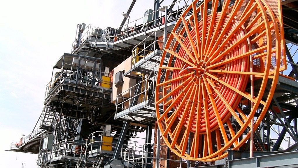
Mobile reel systems play a critical role in numerous industrial applications, from bustling seaports to demanding mining operations. These systems facilitate the efficient transfer of power and data through specialized cables that must withstand repeated coiling and uncoiling. Among the various factors affecting system reliability and safety, cable bending stands out as particularly significant.
This article provides in-depth technical guidance on "maximum allowable sidewall pressure" and practical calculation methods to determine it. Whether you're an engineer, technician, or industry professional, you'll gain valuable insights into design verification techniques that enhance both engineering efficiency and operational safety.
I. Basic Concepts and Terminology
1.1 Reel Cable Fundamentals
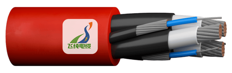
Unlike standard towing cables, reel cables are engineered specifically for dynamic applications involving continuous bending cycles. These specialized cables feature distinctive structural characteristics including:
Enhanced flexibility through specialized materials and construction
Optimized core configurations (typically 3-5 cores)
Variable cross-sectional areas based on load requirements
Reinforcement layers for tension resistance
The specific combination of materials, number of cores, and cross-sectional design directly impacts a cable's performance under bending stress.
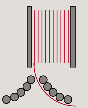
1.2 Understanding Bending Radius and Sidewall Pressure
Minimum bending radius represents the smallest curve a cable can safely conform to without sustaining damage. When a cable bends, complex mechanical forces develop:
The outer layer experiences compression
The inner layer undergoes tension
The neutral axis (center) remains relatively unstressed
Sidewall pressure occurs at the contact point between the cable and the supporting surface (typically the reel drum). This pressure is the critical force that, when excessive, can lead to cable failure through sheath deformation, core displacement, or insulation damage.
1.3 Industry Standards for Maximum Allowable Sidewall Pressure
Several authoritative organizations have established guidelines for sidewall pressure limits:
IEC 60794 recommends specific values based on cable construction
API standards provide industry-specific guidance for petroleum applications
Feichun Cable technical specifications offer manufacturer-validated thresholds
The generally accepted limits are:
7300 N/m (500 lb/ft) of radius for multiconductor power cables and single-conductor power cables 6 AWG and larger
4380 N/m (300 lb/ft) of radius for control cables and single-conductor power cable 8 AWG and smaller
Instrumentation cables require manufacturer-specific recommendations
II. Key Factors Affecting Sidewall Pressure
2.1 Cable Structural Parameters
The cable's physical composition dramatically influences its response to sidewall pressure:
Sheath Material Impact:
PUR (Polyurethane) sheaths offer excellent abrasion resistance but lower flexibility
CPE (Chlorinated Polyethylene) provides better chemical resistance with moderate flexibility
Structural Elements:
Multi-layer construction distributes stress differently than simple designs
Steel wire reinforcement layers significantly increase bending resistance
Cable diameter directly affects the contact surface area with the drum
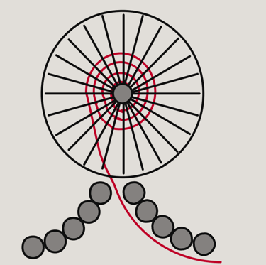
2.2 Drum Design Parameters
The physical characteristics of the reel drum create the environment for sidewall pressure:
Drum diameter (D) establishes the fundamental bending curve
Wall thickness impacts vibration absorption and heat dissipation
Groove type and inclination affect cable alignment and pressure distribution
Different contact modes between cable and groove wall produce varying pressure profiles:
Single groove: Concentrated pressure at specific points
Double groove: Distributed pressure across broader surfaces
Multi-groove: Complex pressure patterns requiring specialized analysis
2.3 Operating Condition Factors
Real-world operation introduces additional variables:
Reeling speed generates dynamic forces that can amplify static pressure
Tension control strategies directly impact sidewall pressure magnitude
Ambient temperature affects material properties and flexibility
Cycle frequency influences fatigue and long-term performance
III. Theoretical Calculation of Maximum Allowable Sidewall Pressure
3.1 Basic Mechanical Model
The fundamental approach to sidewall pressure analysis stems from the Euler–Bernoulli bending beam model, which provides a mathematical framework for understanding the relationship between applied forces and material deformation.
The key relationship can be expressed as:
Sidewall pressure (P) is directly related to the bending moment (M), the distance from the neutral axis (y), and inversely related to the moment of inertia (I) of the cable cross-section.
3.2 Analytical Calculation Steps
To determine the maximum allowable sidewall pressure:
Determine the minimum bending radius (r) based on cable specifications
Calculate the bending moment using M = E·I / r, where E is the elastic modulus
Calculate the sidewall pressure using the appropriate formula:
Single cable in conduit: P = T₀ / r
Three cables in cradle configuration (center cable experiences highest pressure): P = (3c - 2)T₀ / 3r
Three cables in triangular configuration (pressure divided between bottom two cables): P = cT₀ / 2r
Four cables in diamond configuration (bottom cable experiences highest pressure): P = (3c - 2)T₀ / 3r
Where:
P is the sidewall pressure in newtons/millimeter (pounds/foot) of radius
T₀ is the tension out of the bend in newtons (pounds)
c is the weight correction factor
r is the inside radius of bend in millimeters (feet)
Compare calculated values with material-specific allowable stress limits
3.3 Nonlinearity and Multi-layer Structure Considerations
Real-world cables rarely conform to simple linear models due to:
Nonlinear superposition effects between steel wire reinforcement and elastic sheaths
Varying elastic properties across different material layers
Complex deformation patterns under load
To account for these complexities, practical correction coefficients must be applied. For example, a multi-layer cable with steel wire reinforcement might require a correction factor of 1.2-1.5 depending on the specific construction details.
IV. Experimental and Numerical Simulation Methods
4.1 Test Bench Layout
Empirical validation remains essential for accurate sidewall pressure assessment:
Strategic placement of pressure sensors at critical contact points
Precision tension measurement devices at cable entry/exit points
Environmental controls to simulate varied operating conditions
Data acquisition systems with sufficient sampling rates to capture dynamic effects
4.2 Finite Element Simulation (FEM)
Modern computational tools offer powerful insights through:
Detailed geometric modeling of cable cross-sections
Material property definitions including nonlinear behaviors
Contact mechanics simulation between cable and supporting surfaces
Boundary condition specifications that accurately reflect operational scenarios
Industry-standard software packages like ANSYS, ABAQUS, or COMSOL provide specialized modules for cable mechanics, though proper meshing techniques are crucial for accurate results.
4.3 Comparison and Verification
The true value emerges when theoretical, experimental, and computational approaches converge:
Cross-validation between calculation methods identifies potential discrepancies
Sensitivity analysis reveals critical parameters for focused optimization
Iterative refinement produces increasingly accurate prediction models
V. Calculation Examples and Operation Guide
5.1 Case Study: Single-layer PUR Sheathed 3C4 AWG Reel Cable
Consider a typical industrial application with these parameters:
Cable diameter: 28.5 mm
Tension: 3000 N
Bending radius: 400 mm
Weight correction factor: 1.15
Step 1: Verify the minimum bending radius compliance (minimum should be ≥ 10× cable diameter) 400 mm ÷ 28.5 mm = 14.04 (✓ Complies)
Step 2: Calculate sidewall pressure for single cable in conduit P = T₀ / r = 3000 N / 400 mm = 7.5 N/mm = 7500 N/m
Step 3: Compare with maximum allowable value 7500 N/m > 7300 N/m (Exceeds limit by ~2.7%)
Solution: Either increase the bending radius to at least 411 mm or reduce tension to maintain safety margins.
5.2 Case Study: Multi-layer Steel Wire Reinforced 5kV High-voltage Reel Cable
For more complex cables:
Cable diameter: 42 mm with steel wire reinforcement
Tension: 4500 N
Bending radius: 600 mm
Configuration: Three cables in cradle arrangement
Weight correction factor: 1.3
Step 1: Verify minimum bending radius compliance 600 mm ÷ 42 mm = 14.29 (✓ Complies)
Step 2: Calculate sidewall pressure with nonlinear correction P = (3c - 2)T₀ / 3r × 1.25 (reinforcement correction) P = (3×1.3 - 2)4500 N / (3×600 mm) × 1.25 P = 5.875 N/mm = 5875 N/m
Step 3: Compare with maximum allowable value 5875 N/m < 7300 N/m (Within acceptable range)
5.3 Common Misunderstandings and Troubleshooting
Several issues frequently arise in practical applications:
Sheath Deformation and Cracking: When cables are forced to bend beyond their minimum radius, progressive damage occurs:
Initial elastic deformation
Microfractures in outer sheath layers
Complete circumferential cracking
Core exposure and failure
Secondary Sidewall Pressure Issues: Improperly managed tension during reeling operations creates unexpected pressure spikes:
Erratic tension control systems
Inadequate servo response times
Insufficient feedback mechanisms
VI. Design Optimization and Engineering Practice
6.1 Sheath Material and Structure Selection
Different operational environments demand specialized material selections:
Seaport Applications:
Enhanced UV and saltwater resistance
Impact absorption for crane-mounted systems
Temperature stability for varied weather conditions
Mining Applications:
Abrasion resistance for rocky environments
Chemical resistance to groundwater contaminants
Flexibility in confined spaces
Cold Climate Applications:
Low-temperature flexibility retention
Ice formation resistance
Thermal cycling durability
6.2 Reel Groove and Tension Control Strategy
Advanced design approaches enhance performance:
Groove Design Innovations:
Helical groove patterns distribute wear more evenly
Variable pitch accommodates cable diameter variations
Composite materials reduce friction and wear
Intelligent Tension Management:
Active feedback systems continuously monitor cable tension
Predictive algorithms anticipate loading changes
Servo-controlled motors provide precise tension adjustment
6.3 Maintenance and Life Prediction
Proactive management strategies extend service life:
Monitoring Solutions:
Embedded pressure sensors provide real-time data
Thermal imaging identifies hot spots before failure
Vibration analysis detects early warning signs
Lifecycle Management:
Precise cycle counting informs replacement scheduling
Progressive inspection protocols identify developing issues
Maintenance intervals tailored to actual usage patterns
VII. Conclusion and Outlook
Understanding and properly calculating maximum allowable sidewall pressure represents a critical engineering discipline for ensuring reliable reel cable performance. By applying the calculation methods outlined in this article, engineers can confidently design systems that balance operational requirements with safety margins.
The future of reel cable technology points toward several promising developments:
Advanced composite materials with enhanced flexibility and durability
Integrated sensor networks for continuous health monitoring
AI-driven predictive maintenance systems
Digital twin simulations for precision engineering
For projects demanding the highest reliability standards, Feichun Cable's professional customization services offer tailored solutions backed by extensive testing and validation. Our engineering team partners with clients to develop cable systems optimized for specific applications, ensuring both performance and longevity.
Appendix
Glossary of Key Terms
Bending Radius: The radius of the arc formed by a cable when bent
Sidewall Pressure: Force per unit length experienced at the contact point between cable and supporting surface
Neutral Axis: The theoretical line within a bent cable that experiences neither compression nor tension
Weight Correction Factor: Multiplier accounting for cable weight effects on tension
Moment of Inertia: Measure of a cable's resistance to bending forces
Essential Formulas
Single cable in conduit: P = T₀ / r
Three cables in cradle configuration: P = (3c - 2)T₀ / 3r
Three cables in triangular configuration: P = cT₀ / 2r
Four cables in diamond configuration: P = (3c - 2)T₀ / 3r
Reference Standards
IEC 60794: Optical fibre cables - Part 1-2: Generic specification - Basic optical cable test procedures
API RP 17E: Specification for Subsea Umbilicals
GB/T 12706: Power cables with extruded insulation and their accessories


Frequently Asked Questions (FAQ)
What is sidewall pressure in reeling cables?
Sidewall pressure is the radial bearing force per unit length exerted at the interface between a cable and the drum or sheave wall when the cable bends under tension, calculated as tension divided by bend radius Classic Wire & Cable..Why is controlling sidewall pressure critical?
Excessive sidewall pressure can deform the outer sheath, crack insulation, expose conductors, and drastically reduce cable service life okonite.com.What is the minimum bending radius for reel cables?
Manufacturers typically specify a minimum bending radius of at least 10 × cable diameter to prevent permanent deformation and insulation damage ELEK Software.How is sidewall pressure calculated for a single cable?
For a single conductor:P=T0r P = \frac{T_0}{r}P=rT0
where PPP is pressure, T0T_0T0 is tension, and rrr is inside bend radius forums.mikeholt.com.
How do I calculate pressure for three cables in cradle configuration?
P=(3 c−2) T03 r P = \frac{(3\,c - 2)\,T_0}{3\,r}P=3r(3c−2)T0
where ccc is the weight correction factor (≈ 1.1–1.3).
What about three cables in a triangular layout?
P=c T02 r P = \frac{c\,T_0}{2\,r}P=2rcT0
reflecting that pressure divides among two bottom cables.
How do you handle four-cable configurations?
Use the generalized cradle formula with appropriate geometric factors or simulate via FEM for complex arrangements.What weight correction factor should I use?
The factor ccc accounts for cable self-weight effects; typical values range from 1.1 to 1.3, determined by cable mass and drum orientation Power and Cables.Which industry standards govern maximum sidewall pressure?
IEEE Std 525–1992 limits to 500 lb/ft (≈ 7300 N/m) for multiconductor power and ≥ 6 AWG single conductors; 300 lb/ft (≈ 4380 N/m) for control cables and smaller gauges.What values do IEC standards recommend?
IEC 60794 series provides generic mechanical requirements but defers pressure limits to manufacturer data and application-specific guidelines.How can I verify pressure limits experimentally?
Install pressure sensors at cable–drum contact points and tension meters at entry/exit; run static and dynamic bending cycles while logging data.What role does finite-element simulation play?
FEM models capture nonlinear material behaviors, contact mechanics, and complex geometries to predict sidewall pressure distribution before prototyping.How do I set up a reliable FEM model?
Define accurate cross-section geometry, layer-specific elastic/plastic properties, contact friction coefficients, and realistic boundary conditions.What common sensors are used for testing?
Thin-film pressure transducers or piezoelectric sensors embed in drum grooves; they must withstand abrasion and moisture.How does sheath material affect sidewall pressure tolerance?
Polyurethane (PUR) sheaths offer high abrasion resistance; chlorinated polyethylene (CPE) excels in chemical resistance—both have material-specific stress limits.When is a nonlinear correction factor needed?
Multi-layer cables with steel wire reinforcement exhibit nonlinear superposition requiring empirical correction factors (1.2–1.5×) in pressure formulas.What's an example calculation for a 3C4 AWG PUR-sheathed cable?
For 3000 N tension, 400 mm radius:
P=3000N/400mm=7.5N/mm≈7500N/mP = 3000 N / 400 mm = 7.5 N/mm \approx 7500 N/mP=3000N/400mm=7.5N/mm≈7500N/m, slight exceedance of 7300 N/m limit.How do I adjust design if pressure exceeds limits?
Increase bend radius, reduce cable tension, switch to more flexible sheath, or add a low-friction liner.What impact does reeling speed have?
Higher speeds introduce dynamic amplification of static pressure; ensure tension control loops can respond within cycle times.How do temperature variations affect pressure?
Cold reduces sheath flexibility, raising effective pressure; hot environments can soften materials, lowering resistance to deformation.What maintenance practices help manage sidewall pressure?
Regular groove inspection, sensor calibration, cycle counting, and thermal/vibration monitoring extend safe service life.How often should I recalibrate pressure sensors?
At least annually, or after any mechanical overhaul, to maintain ± 5 % accuracy under field conditions.Can I use digital twins for monitoring?
Yes—integrating real-time sensor feeds into a virtual FEM model enables predictive alerts on over-pressure events acome.com.What groove designs minimize peak pressure?
Helical and variable-pitch grooves distribute contact forces; composite liners reduce friction and wear.How do I choose a tension control strategy?
Servo-motor drives with PID or model-predictive control maintain target tension with minimal overshoot and oscillation.What testing standards apply to optical reeling cables?
IEC 60794-1-21 Method E24 defines microduct blowing tests; other parts cover mechanical bending and cyclic fatigue.How is cable life predicted?
Develop S–N curves (stress vs. cycles) from bending tests and apply Miner’s rule for cumulative fatigue damage.What common misconceptions exist?
Assuming static bend radius alone ensures safety; actual damage often arises from localized pressure spikes during dynamic operation econline.com.How do environmental contaminants affect sidewall pressure?
Salt, dust, and chemicals can alter friction coefficients and wear rates, raising pressure and abrasion risk ELEK Software.What are typical failure modes from over-pressure?
Sheath extrusion, longitudinal core displacement, insulation cracking, followed by partial or total circuit failure.How does cable diameter influence pressure?
Larger diameter increases contact surface, reducing pressure for the same tension and radius; small-gauge cables concentrate force forums.mikeholt.com.Should I derate tension in multi-layer cables?
Yes—apply manufacturer-recommended derating factors to account for reduced flexibility and complex stress paths NRC Web.What role do lifecycle management systems play?
Integrating cycle counts, sensor logs, and maintenance history optimizes replacement intervals and reduces unplanned downtime Southwire | Homepage.How do I address pressure in subsea reeling applications?
Use pressure-compensated sheathing, corrosion-resistant alloys, and specialized low-friction liners to handle hydrostatic and sidewall loads.How can I engage Feichun Cable for custom solutions?
Contact Feichun’s engineering team with your application parameters; they’ll provide tailored calculations, materials selection, and prototype testing under your specific operating conditions.
References:
Elek Software, “Cable Pulling Tension and Sidewall Pressure Calculations,” elek.com ELEK Software
Okonite, “Sidewall Pressure Limitations,” okonite.com
Classic Wire & Cable, “Handling and Installation Engineering Guide,” Classic Wire & Cable.
Southwire, “Maximum Pulling Tension,” Southwire | Homepage
Power & Cables, “Cable Pull Calculations,” Power and Cables
Mike Holt Forums, “Sidewall Pressure Equations,” forums.mikeholt.com
EC Online, “Calculating Cable Pulling Tensions,” econline.com
NRC, “Cable Sidewall Bearing Pressure Tests,” NRC Web
IEC 60794-1-1, generic optical fibre cable specs
IEC 60794-1-21, microduct blowing test Method E24


Reeling Cable Bending: Maximum Allowable Sidewall Pressure and Calculation Methods
Comprehensive guidance on reeling cable bending, including maximum allowable sidewall pressure definitions, analytical and experimental calculation methods, practical case studies, and design optimization tips to ensure reliable and safe reel cable performance in industrial applications.
5/1/202511 min read